The Hula Loop AntennaShortwave DX from an urban canyon, using a magnetic loop antenna:
design considerations and observations
By Gert Stange DG5GS
Introduction. Given the basic properties of the propagation of electromagnetic
radiation, it is desirable that the antenna of a radio system is of dimensions
that are in the order of the wavelength used, and it is equally desirable that
the antenna is placed sufficiently high, above and far away from surrounding
obstacles. The smallest wavelength normally useable for DX amateur radio is
approximately 10 m, seemingly giving little chance to even trying to establish
contacts under space constraints below that.

The present report aims at demonstrating that this is not the case, and that
reasonable results can be achieved, using low bandwidth transmission modes.
Simultaneously, emphasis is given to the demonstration that this is possible
using a magnetic loop.

Advantages of magnetic loops are their compact size, the absence of a need for
a ground connection, and the ability to be tuned over a wide frequency range,
a factor of 3 being easily achievable. Major disadvantages are the extremely
low radiation resistance, requiring low-loss construction, and the extremely
narrow bandwidth, raising the need for the appropriate effort with the construction
of the tuning assembly. One aim of the present communication is to particularly
address those constraints.
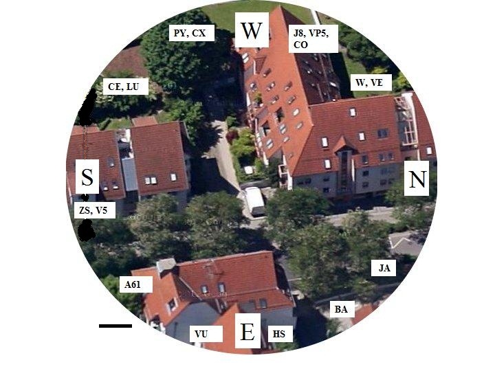
Fig.1.
Bird's eye view of QTH, at JN48ko, facing west, taken at a date prior to the
erection of the antenna, which is currently located next to the small white rectangle
at the centre. The surrounding buildings are approximately 12 m high; the direction
of least obstruction is to the W/SW. The bearings of several countries are indicated
by the prefixes at the periphery.
Scale bar: 5 m.
 -
-
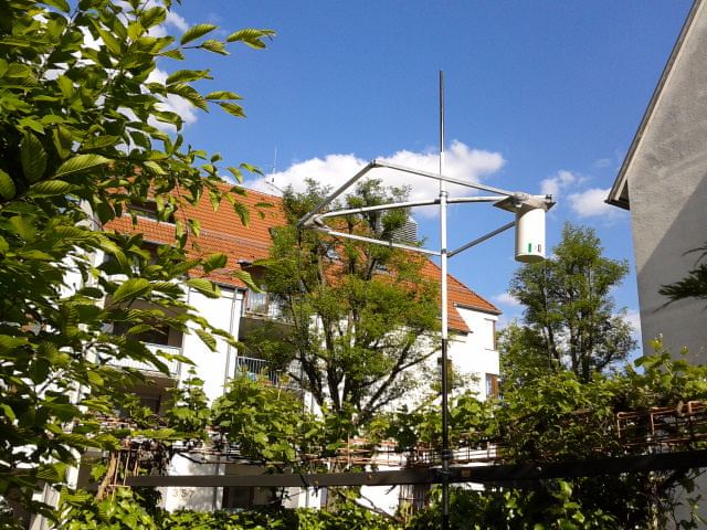
Fig.2.
View of antenna site from W. Earlier version of mag loop, constructed from 800 mm
sections of 15 mm square aluminium profiles. Sections were bolted together and
could be disassembled for transport. The piece of large diameter tubing contains
tuning capacitor and gear motor. The loop is mounted horizontally on a telescopic
GFK mast, 3.5 m above ground and 1.5 m above the upper edge of iron grid fence.
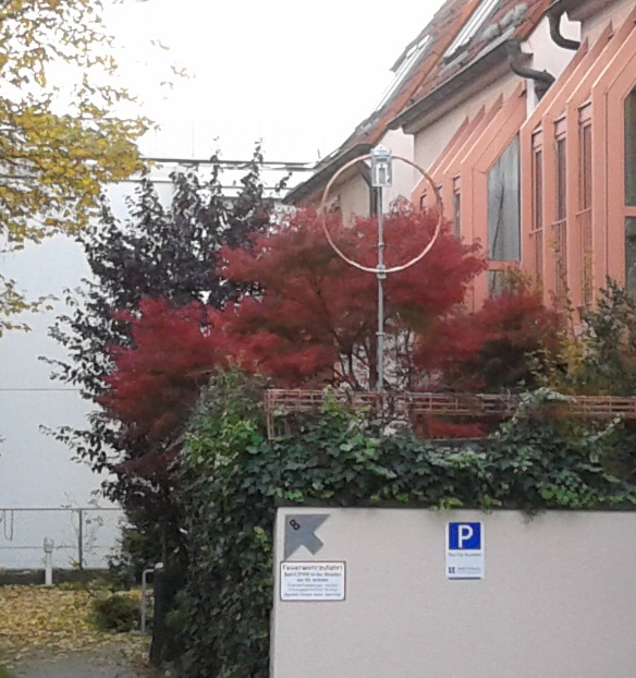
 Fig.3.
View of antenna site from E. Improved version of mag loop, constructed from the
plastic core of a hula hoop, diameter 1 m, with the foam lining removed. The
hoop could be disassembled into 6 sections. An uninterrupted conductive coating
over nearly 360 degrees was obtained by lining the hoop lengthwise with two
pieces of self-adhesive copper tape, 50 mm wide and 15 microns thick. At this
thickness, the conductance of the resulting copper sheath (diameter 25 mm) is
close to that of a much heavier solid rod, given the depth constant of the skin
effect at 14 MHz and above. The box is carved to shape from a 80 mm thick piece of
polystyrene foam, sandwiched between Perspex plates and sealed with ducting tape,
to form a lightweight and watertight housing for tuning capacitor and motor. The
loop is mounted vertically on the GFK mast at heights as above. The assembly,
including the mast and 5m of cabling, weighs 4.2kg.

Fig.4.
Circuit of motor driver. Momentary pushbutton switches control the FWD/REV
polarity inverter and the voltages applied to the motor, via a power Darligton
emitter follower. The driving voltage applied via the SLOW button can be
adjusted by a potentiometer, to a point where the motor is just turning.
FAST is provided to maximize response speed.
Results.

Tuning the loop. A split rotor tuning capacitor(Schubert-Gehaeuse DKS4),
capacitance 2 * 8-130 pf, voltage rating 4 kV, is used. With the hula loop,
this was a sufficient capacitance range to cover the amateur bands from 14 to
29.7 Mhz. At the same time, the voltage rating is sufficient to handle 70 W
on 14 MHz and 150 W on 28 MHz, according to the loop calculator by dg0kw.
Initially, a 12 V gear motor of ratio 600:1 was used, but this ratio was
found to be insufficient at 28 MHz, leading to the replacement by a 3000:1
motor (MFA/Como Drills 3000:1). With this, using the circuit in Fig. 4, it
was possible, after a modicum of getting used to backlash and overshoot, to
readily tune the loop to the respective VSWR minimum at any frequency.

Close vicinity behaviour. It is sometimes asserted that the power radiated
from a magnetic loop is entirely magnetic and will therefore penetrate, with
little loss, a Faraday cage type electrical shield, such as the walls of a
reinforced concrete building, or the grid fence in the current location.
However, this applies only as long as the shield is within the near field of
the radiator: beyond the far-field transition distance, which is in the order of
one wavelength or less (1) (2)), a Maxwellian electromagnetic field has formed,
meaning that it makes no difference of whether the field has originated from a
magnetic loop or an electrical dipole.

Without relying on highly variable quantitative measurements such as S-meter
readings, it can be stated that 2-way contacts were possible regardless of
whether the loop was above or below the upper edge of the fence, or whether
it was actually used from indoors. The present investigation aims at assessing
the suitabilty of a setup that was also spatially restricted in the vertical,
and the arrangement shown in Figs. 2 and 3 was selected as a reasonable
compromise.

Contacts made.The project was commenced in Oct 2012, using SDR software
throughout. The goal of accumulating confirmed 2-way contacts with 100 DXCC
entities was achieved in Dec 2014. In addition, reception only of a further 64
entities was recorded.

The transmitted power was 50W on 30 and 20m, dropping to 20W on 10 m. CW was
exclusively used for the first 15 months. Prefixes worked during that period
were mostly within a range of 5000 km. After that, digital modes were used, namely
RTTY, PSK31 and mainly JT65. This coincided with success in working DX,
including VK long path, JA, CE, ZS, BA, Antarctica. Contacts with the Caribbean
and northern SA were quite common, coinciding with the direction of least
obstruction (Fig. 1). Notably absent were the west of North America and KH.

A horizontal mag loop is omnidirectional in azimuth, whereas the vertical
arrangement has got maxima along the plane of the loop. There was no indication
that either orientation would yield better results. Mostly, the loop was used
in the vertical arrangement, with its plane aligned E-W, the least obstructed
orientation (actually perpendicular to what is shown in Fig. 3). Usually, no
attempts were made to obtain data on directionality in azimuth, with the
exception of a casual contact with ZS, located due south, where reception was
much better for the E-W orientation rather than N-S. This would suggest that
the large building directly to the S is an effective shield and that
propagation was mostly via scatter or reflection.

It may be argued that success of a low-power, low radiation efficiency system
is actually the result of much larger effort invested by the partner stations.
However, successful contacts were made with stations that used no more than
100 W of transmitted power, and in many cases used simple dipoles, the most
outstanding example being VK1 long path.